Unit 211, 1865 Osler St., Regina, SK, Canada S4P 1W1
Patent-Pending Amphibious Architecture

The Hydro-Terran Drive

An individual wheel-based drive mechanism delivering synchronized oleo-pneumatic suspension, high-speed terrestrial traction, water-jet marine thrust, and submersible operation using a single unified powertrain.

Unified Amphibious Powertrain

Eliminating dual-drivetrain weight and mechanical complexity through design science. [View Cinematic Inspiration]

01

Terrestrial Stance

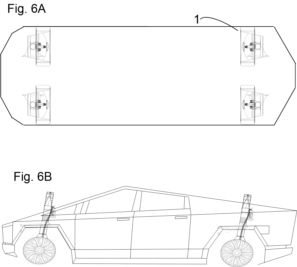
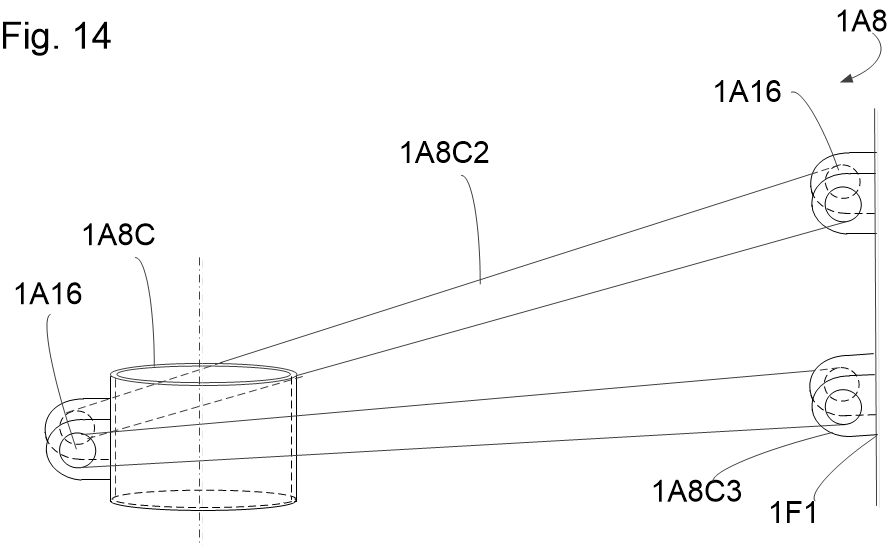
Operates as a high-performance EV wheel assembly with an in-wheel motor, steer-by-wire torque vectoring, sleeve-to-chassis-mounted rake linkages, and active oleo-pneumatic cushioning.

02

Aquatic Pump-Jet

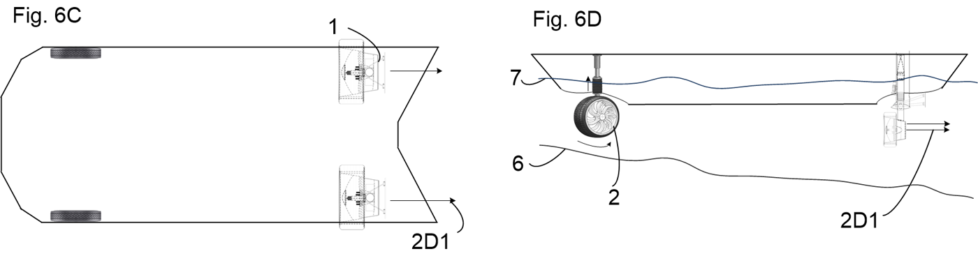
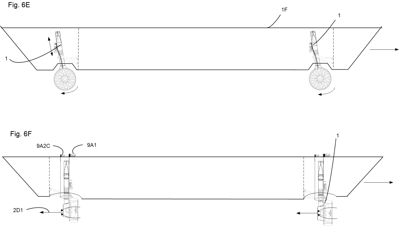
Rotates 90 degrees around its vertical suspension axis and descends into the waterline, converting custom wheel spokes into axial water-jet impellers.

03

Submersible Flight

Simultaneously deploys incidence-controlled hydrofoils to slash hydrodynamic drag above water, or achieve full 3D pitch and roll control underwater.

Strategic Inflection Point

The Convergence: Why the Time is Now

We are witnessing a profound technological alignment. Battery energy density is climbing relentlessly while production costs plummet. Simultaneously, commercial solid-state batteries have arrived, shattering previous safety and capacity ceilings, while electric motors grow exponentially more powerful, efficient, and lightweight.

This is the definitive death knell for the Internal Combustion Engine—and the ultimate killer app for electric mobility.

The Hydro-Terran Drive capitalizes directly on this historic transition. By unifying high-speed terrestrial traction and pump-jet marine propulsion into a single, modular in-wheel powertrain, it liberates electric vehicles from land-locked boundaries. A less expensive, higher-efficiency EV can now seamlessly transition onto—and under—the water.

Intellectual Property

Patent Pending

Invention: The Hydro-Terran Drive: An individual wheel-based drive mechanism that enables efficient and effective suspension and propulsion of suitably equipped vehicles on land, water, and underwater using substantially the same mechanisms.

  • Core Novelty: Coaxial suspension rotation, spoke impellers, and synchronized hydrofoil sleeves.
Key Architectural Features
• 3-Cylinder Coaxial Nested Suspension
• 90° Electromagnetic Engagement Pin Channel
• Spoke-Integrated Water-Jet Rotor Blades
• Synchronized Hydrofoil Deployment Assembly
• Emergency Firefighting / High-GPM Water Manifold

Engineering & Mechanical Systems

Three interconnected subsystems form the foundation of the Hydro-Terran drive architecture.

Subsystem 01

Tri-Cylindrical Oleo-Pneumatic Suspension

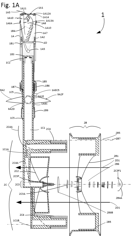
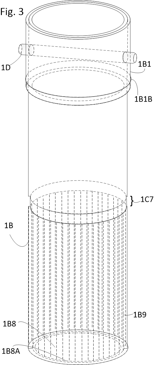
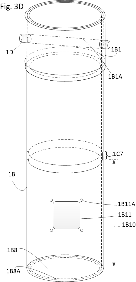
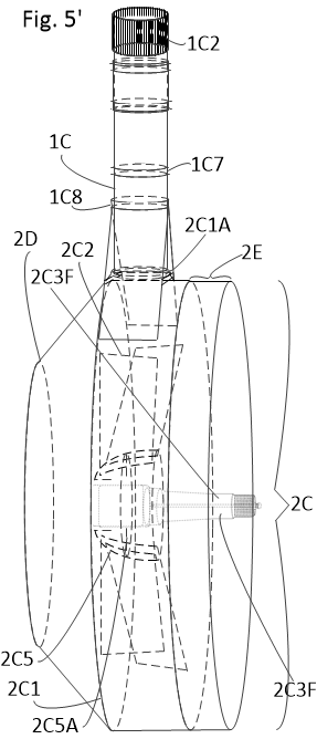
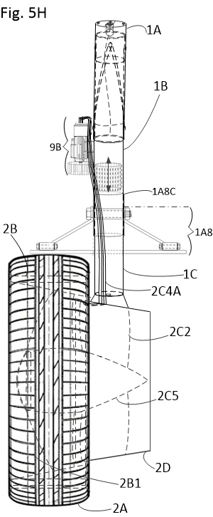
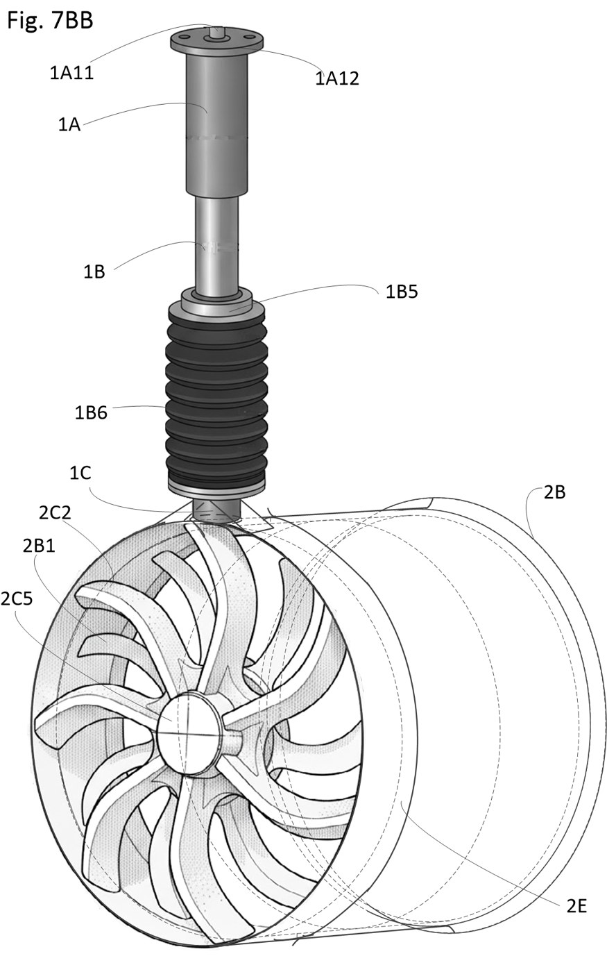
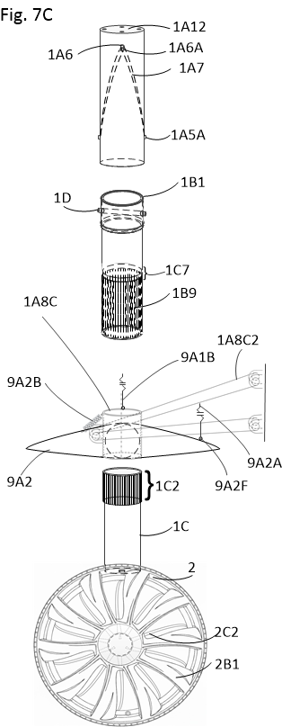
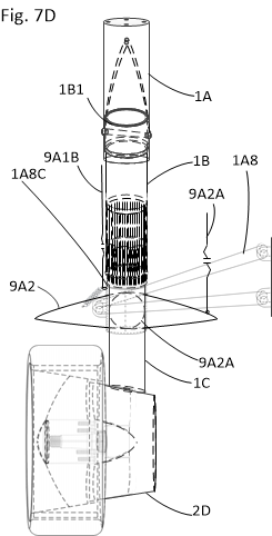
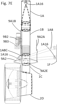
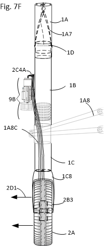
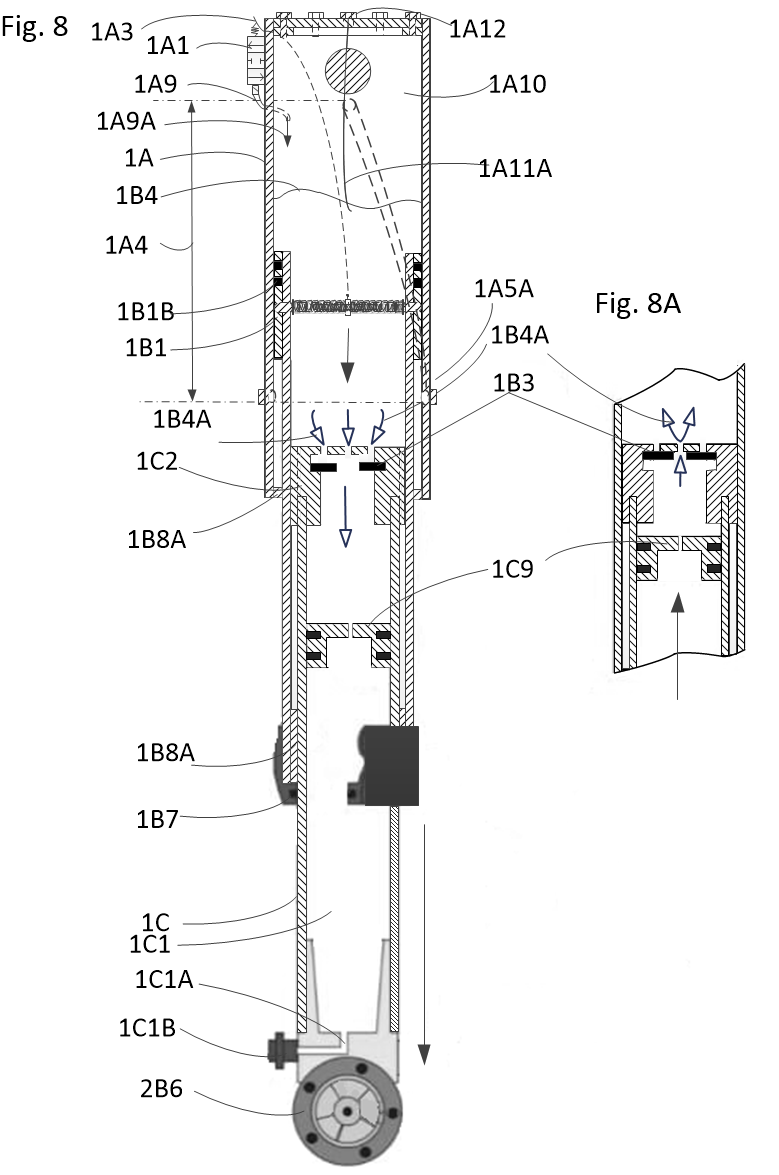
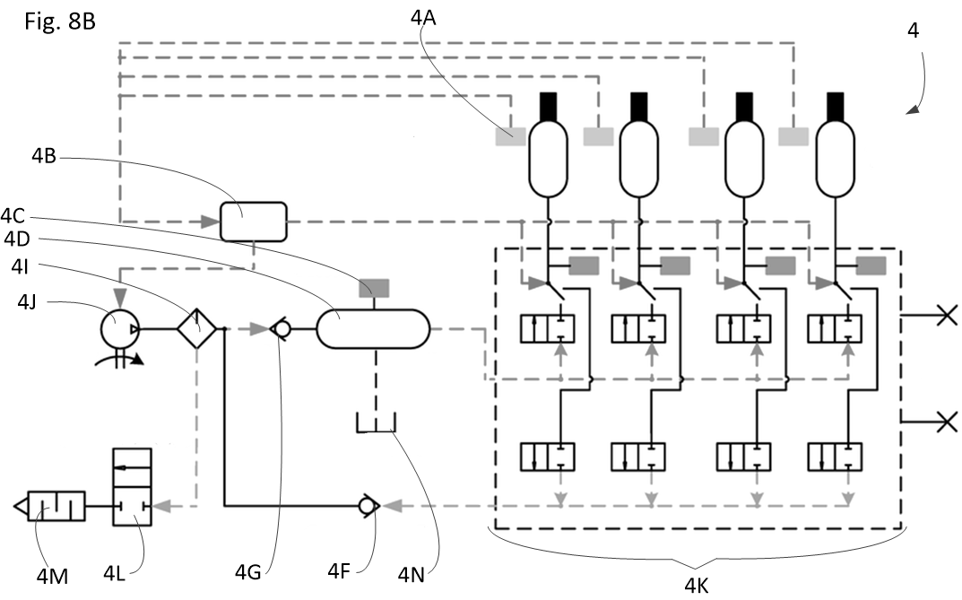
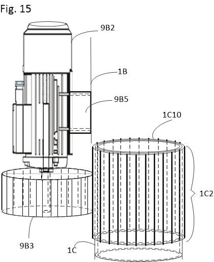
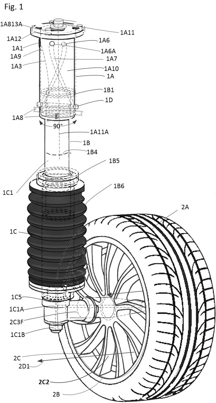
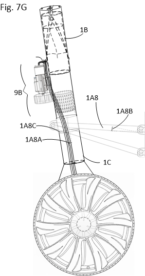
Three coaxial stainless-steel cylinders (Upper 1A, Middle 1B, and Lower 1C) provide variable pneumatic and oil damping—mirroring aircraft landing gear architecture—while functioning as the primary actuator for amphibious redeployment.

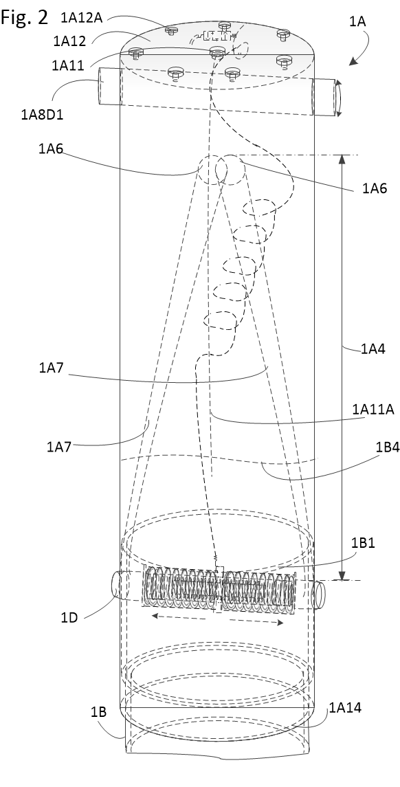
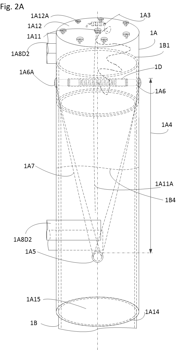
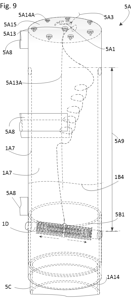
  • Upper Cylinder (1A): Houses internal spiral guide channels (1A7) cut to a depth of at least 1.5 mm, guiding vertical displacement and a 90° axial turn.
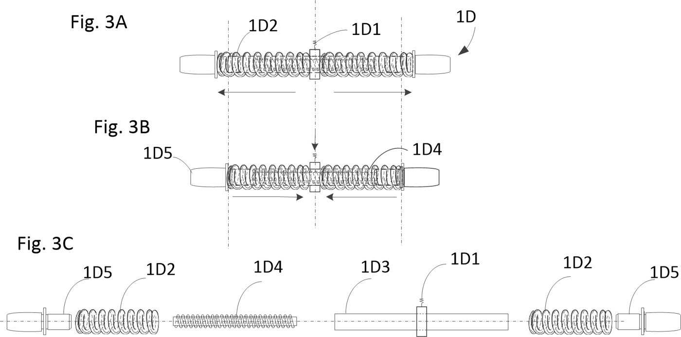
  • Dual-Ended Electromagnetic Pin (1D): Spring-extended (1D2) into upper land holes (1A6) or lower water holes (1A5). Solenoid energization retracts pin tips (1D5) to traverse guide channels.
  • Sealed Integrity: Flexible rubber bellows (1B6) with retaining rings (1B5, 1C5) protect oscillating slide joints against pressurized salt water and road grit.
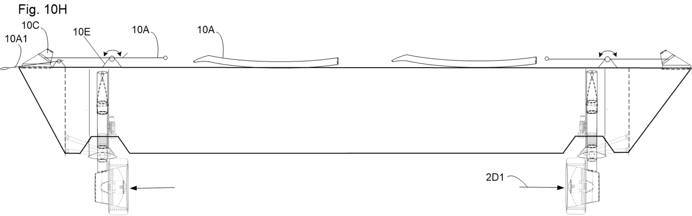
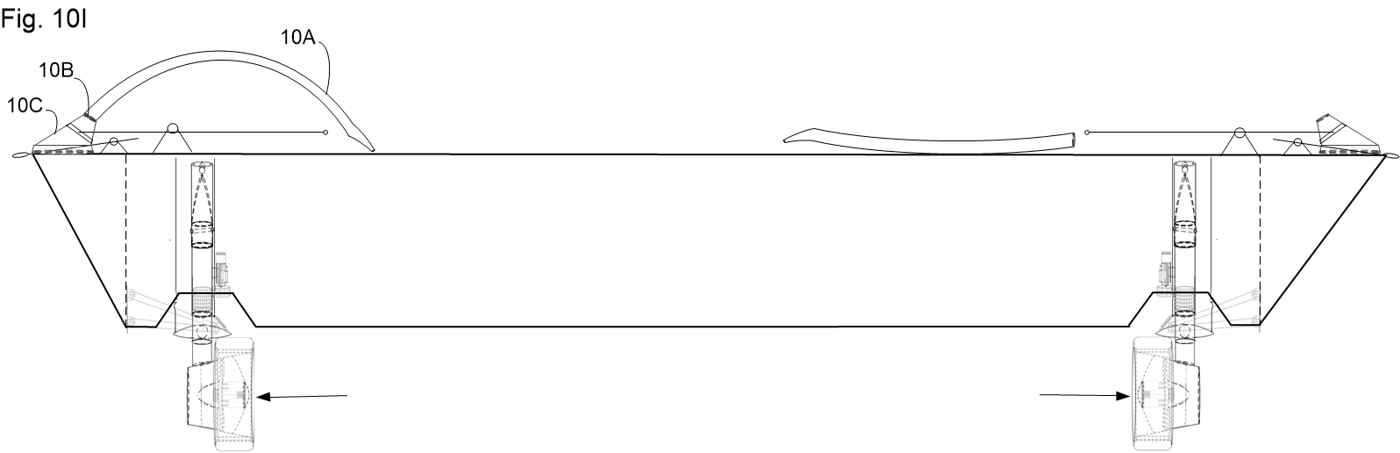
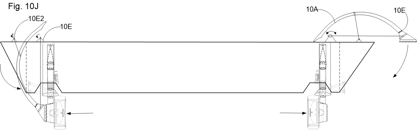
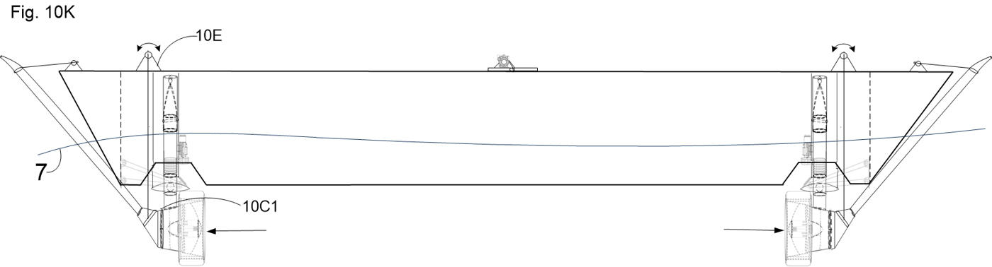
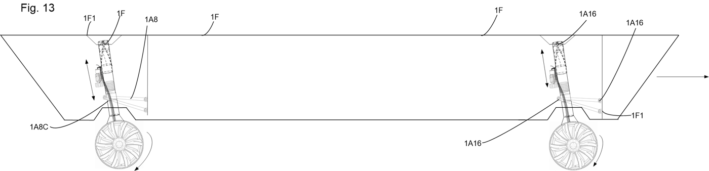
Side view: the drive on land and in water
Subsystem 02

Dual-Mode Wheel / Pump-Jet Impeller

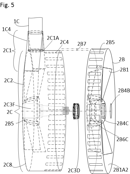
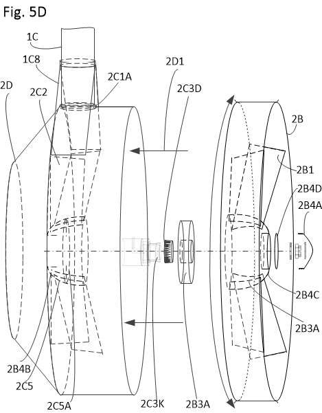
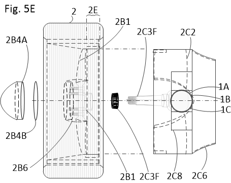
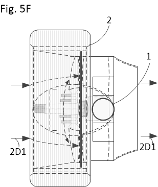
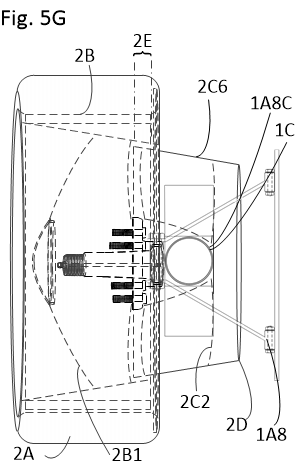
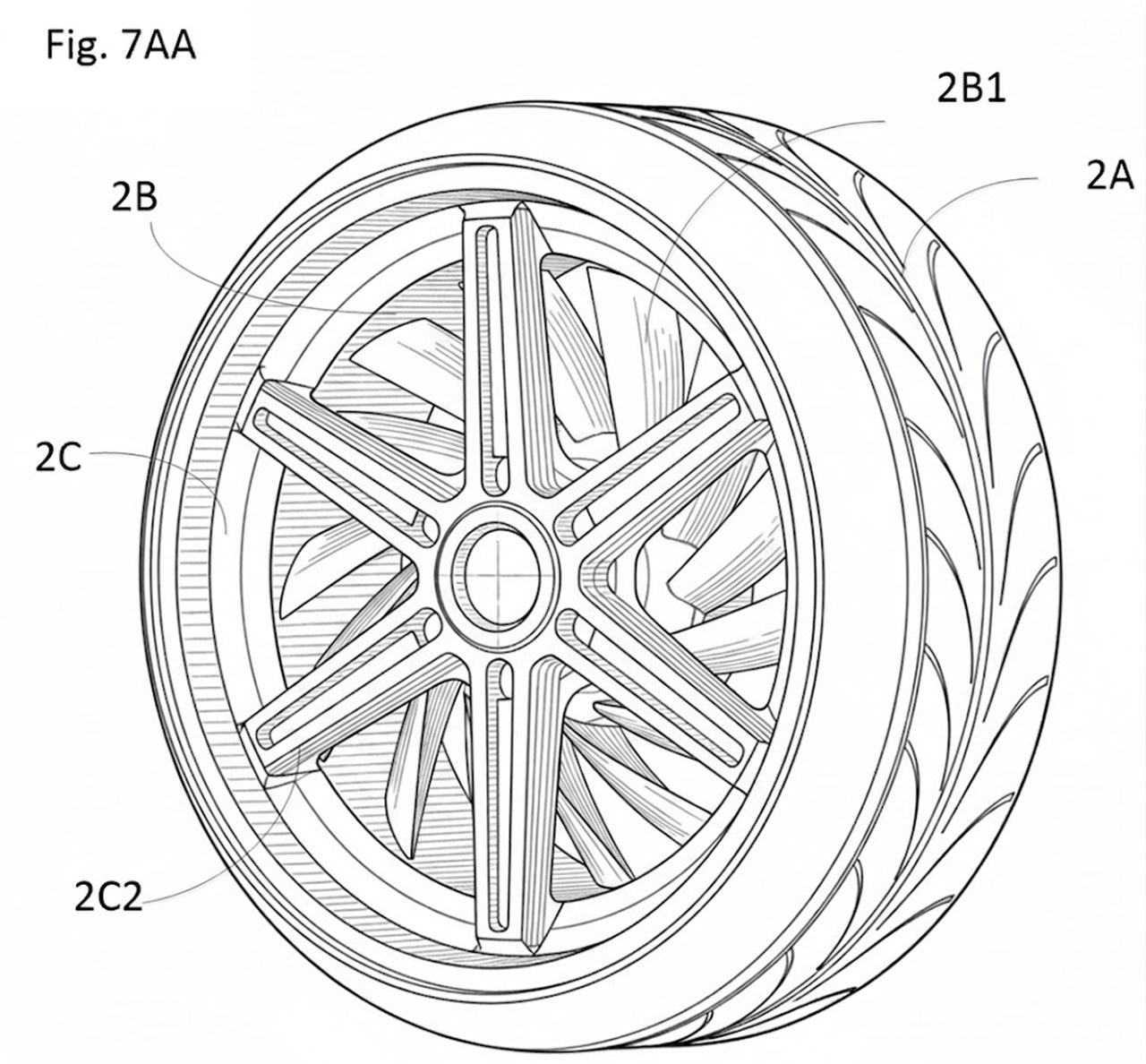
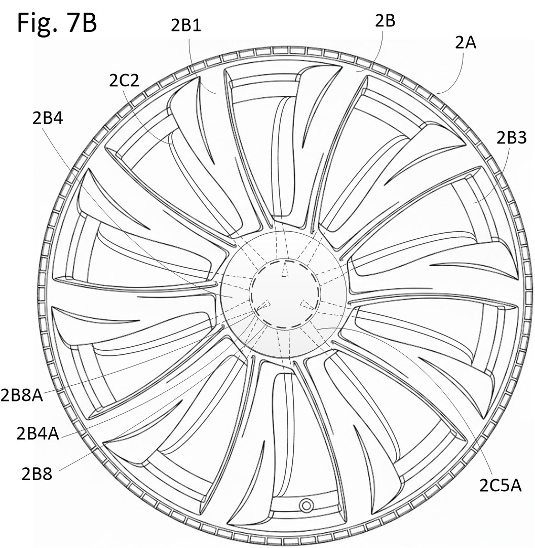
By integrating an axial flux or peripheral motor directly into the rim structure, the center spoke area functions as an unoccluded, high-throughput fluid propulsion corridor.

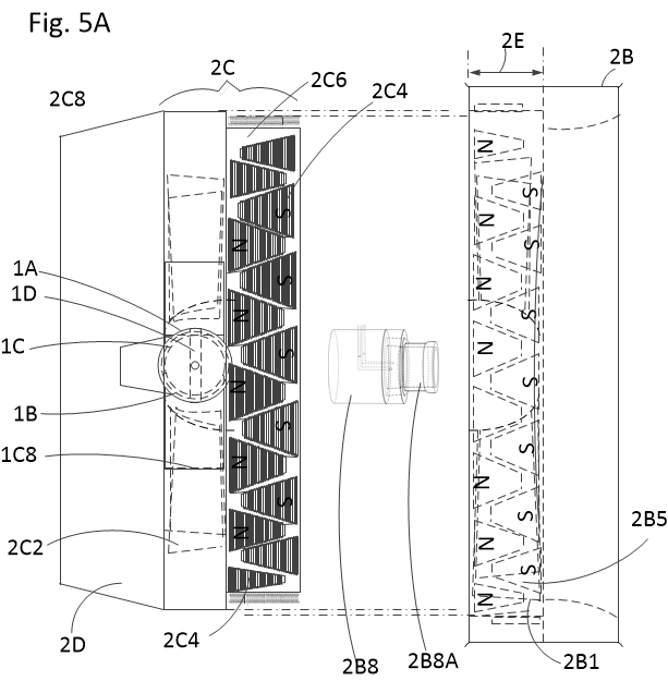
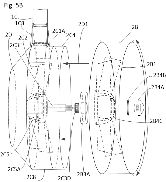
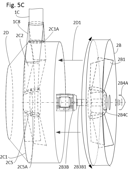
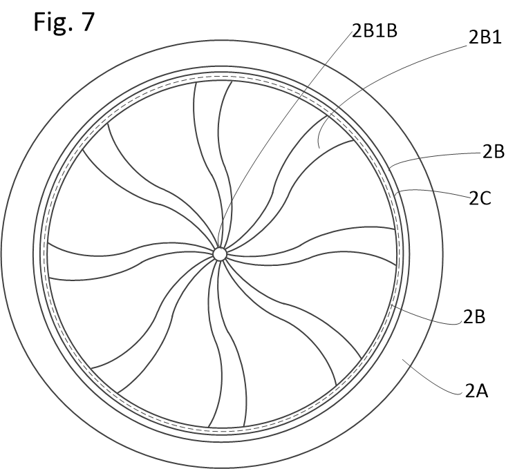
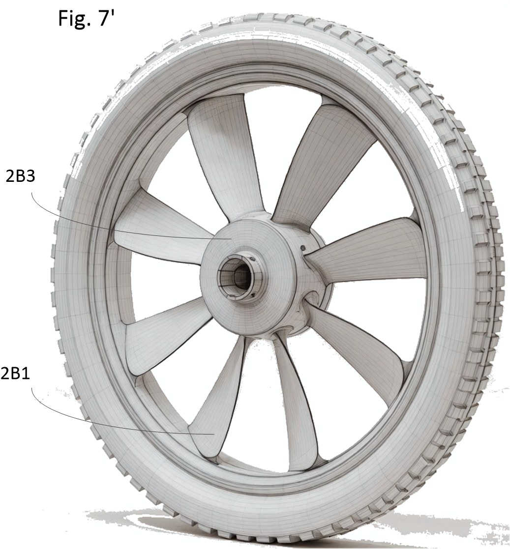
  • Rotor Blades (2B1): Hydrodynamic profiles carry vehicular road shock on land and generate powerful axial-flow thrust (2D1) when submerged.
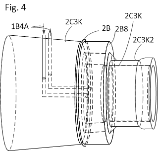
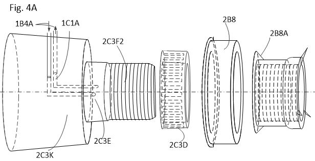
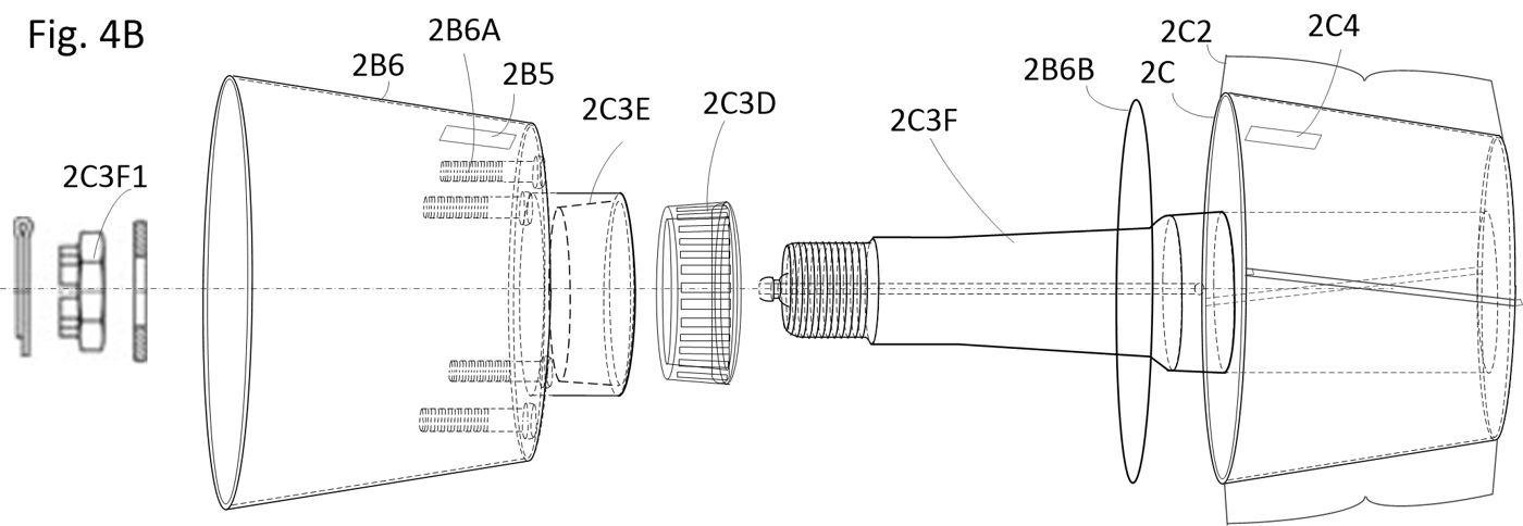
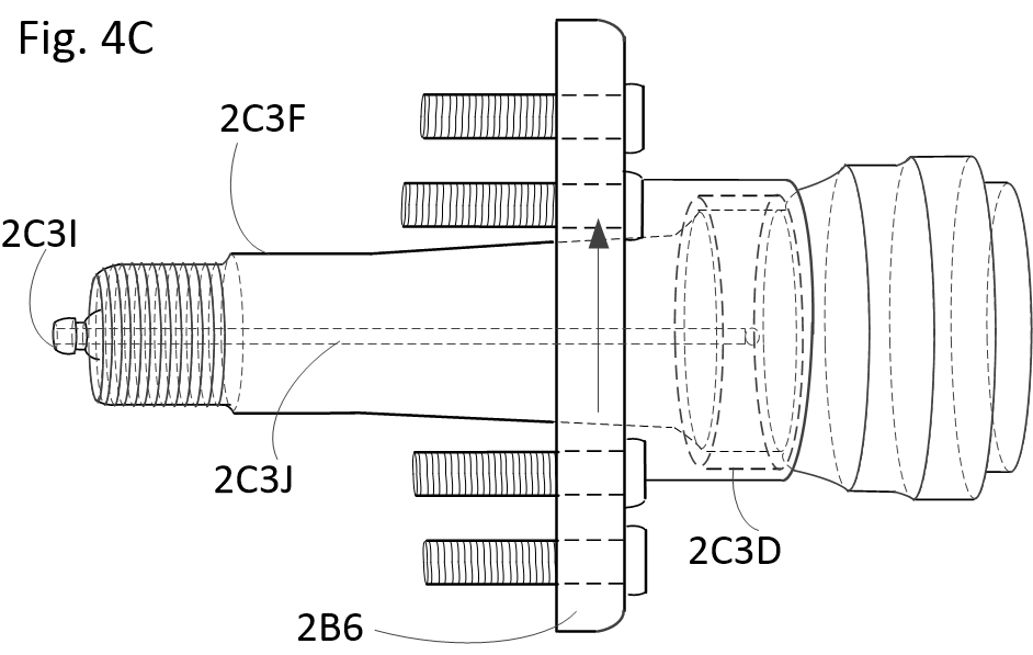
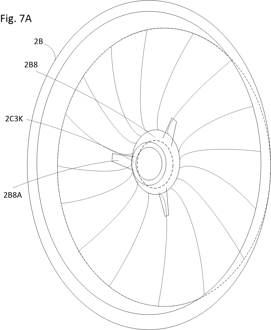
  • Stator Vanes as Structural Supports (2C2): Rigidly connect the outer rim (2C8) to the central spindle (2C3F), functioning as structural load-bearing components while converting swirling propulsive wash into straight, laminar jet thrust.
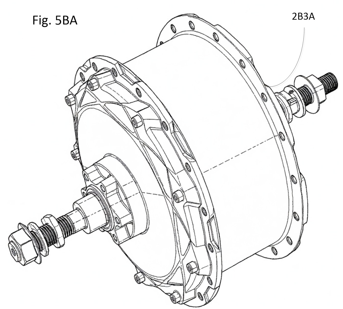
  • Motor Adaptability: Accommodates peripheral magnetic arrays, compact axial flux motors (2B3A), radial flux motors (2B3B), and bilateral axle drives.
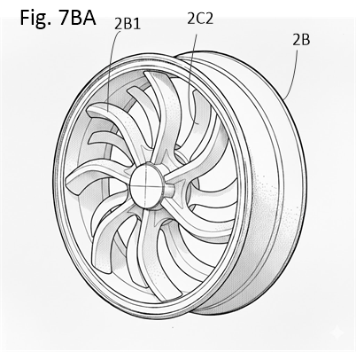
Fig 7BA Wheel Impeller Fig. 7BA — Wheel Rim / Water-Jet Impeller
Subsystem 03

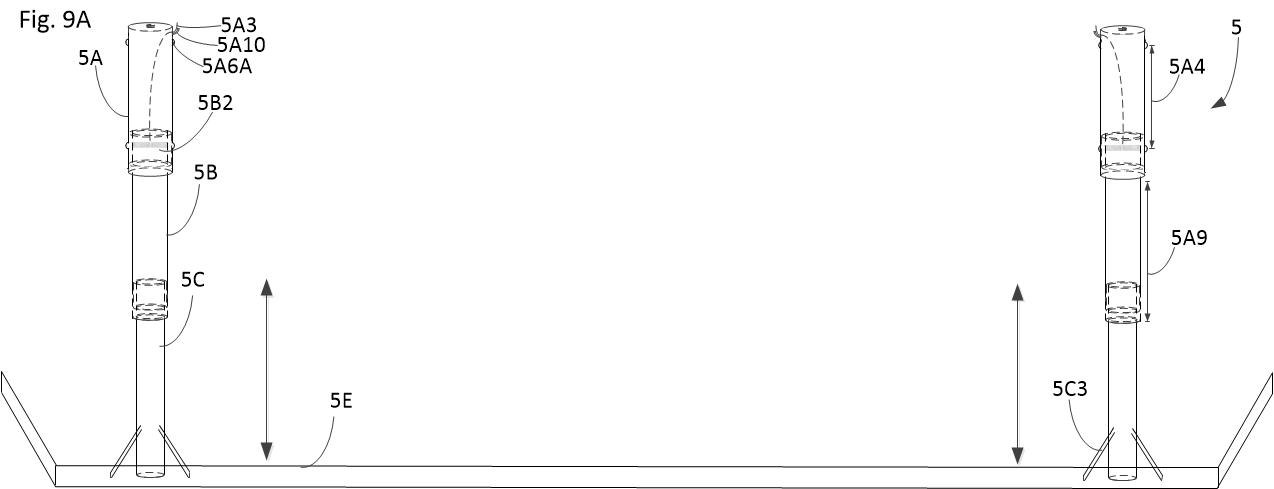
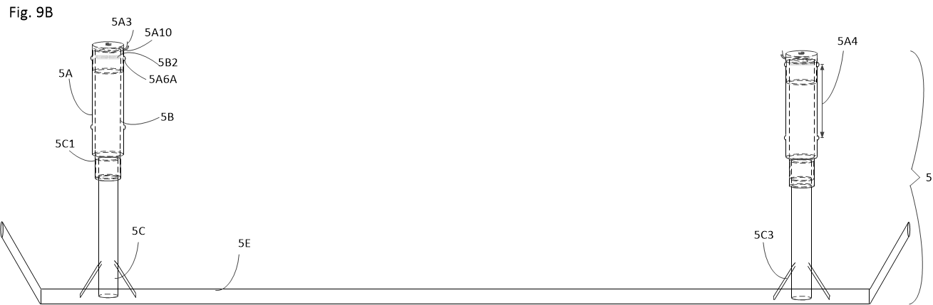
Synchronized Hydrofoils & Steer-By-Wire

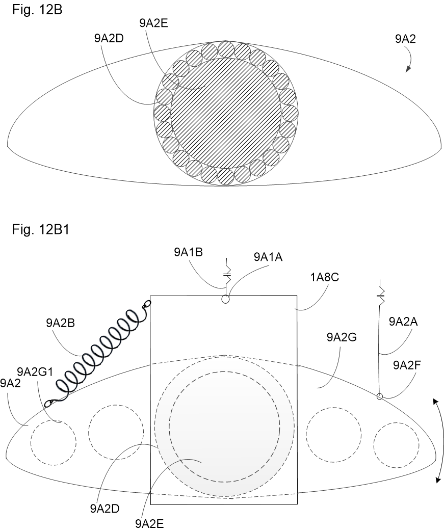
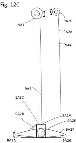
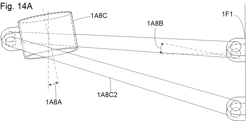
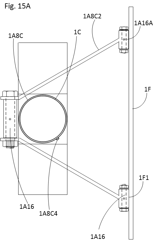
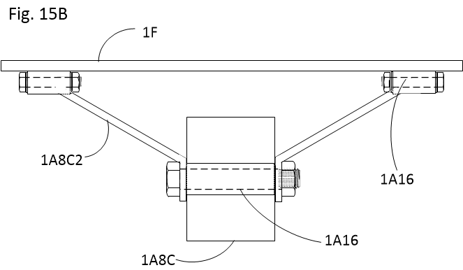
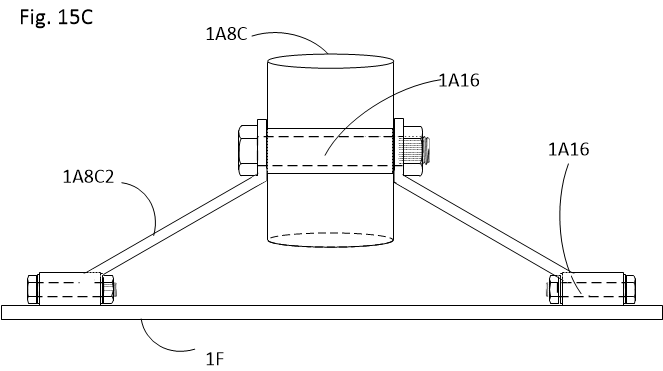
Connected directly to cylindrical sleeves on the lower suspension, the hydrofoils are deployed simultaneously with the drives when entering water mode. Water is roughly 800 times denser than air, so a hull pushing through it wastes a great deal of energy. The hydrofoils lift the hull clear of the water, leaving only the foils and struts below the surface, which is what allows much higher speeds on the water.

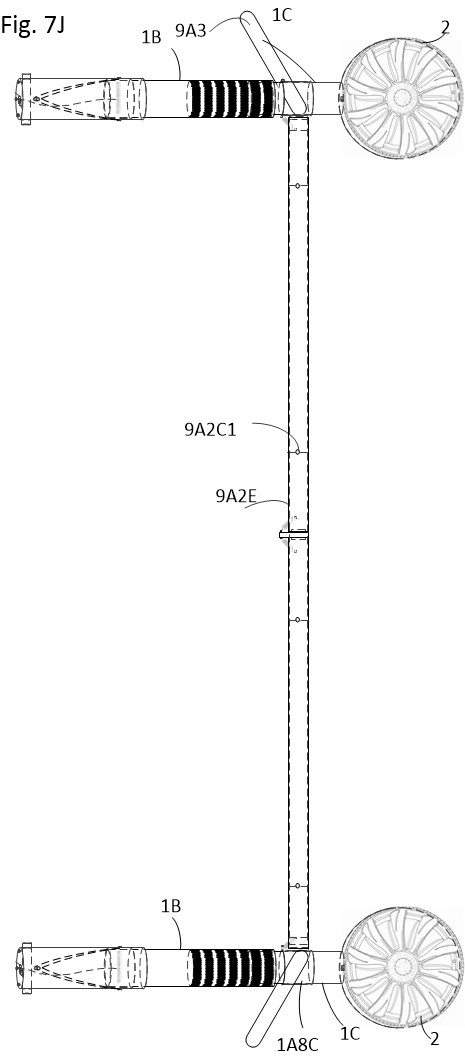
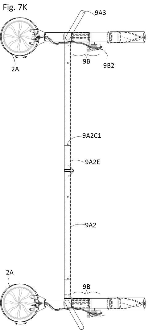
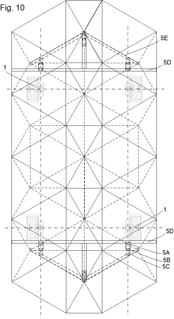
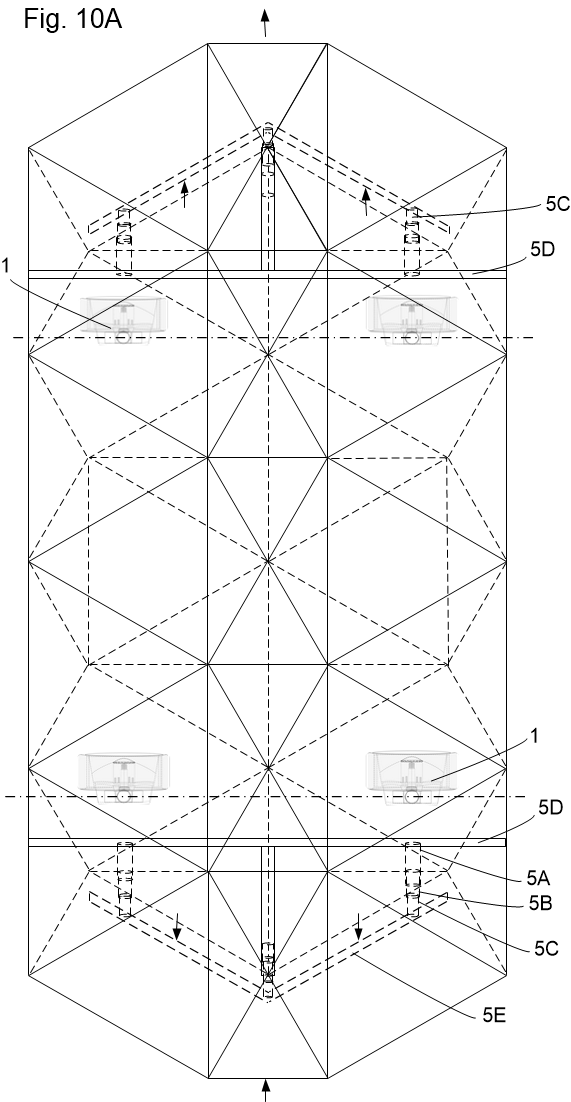
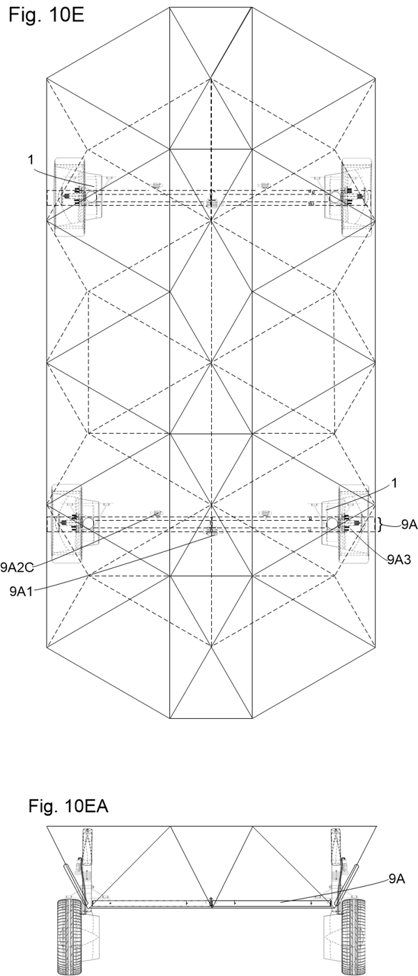
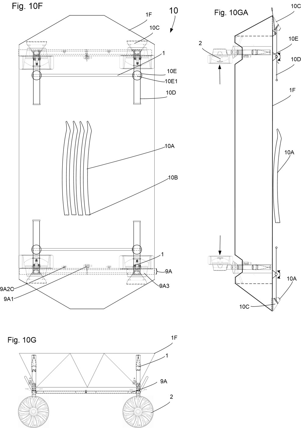
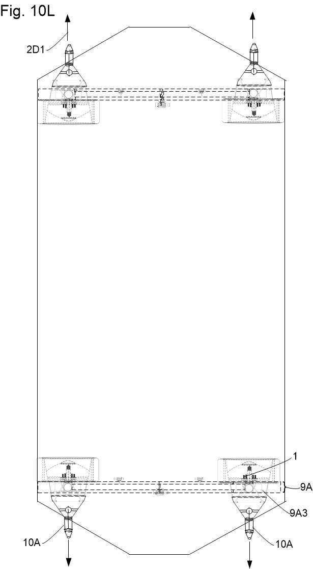
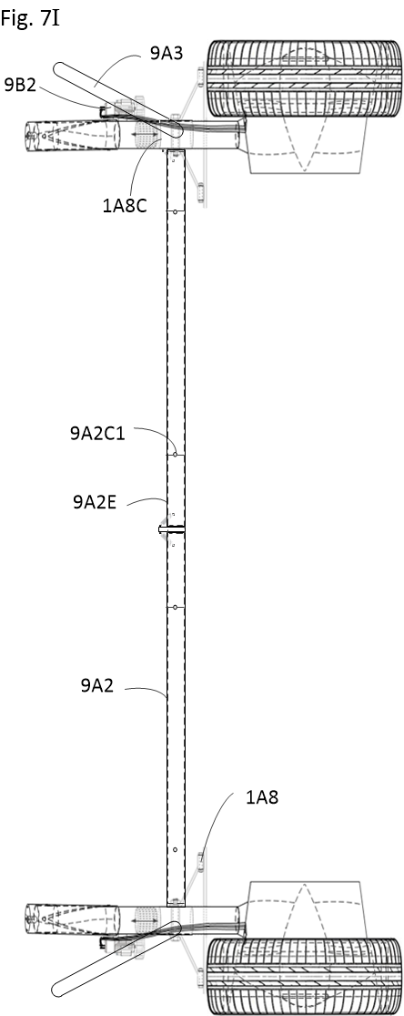
  • Synchronized Marine Flight: Deploys simultaneously with the wheel assemblies via unified chassis winches and spreader bars to lift the hull clear of the water surface.
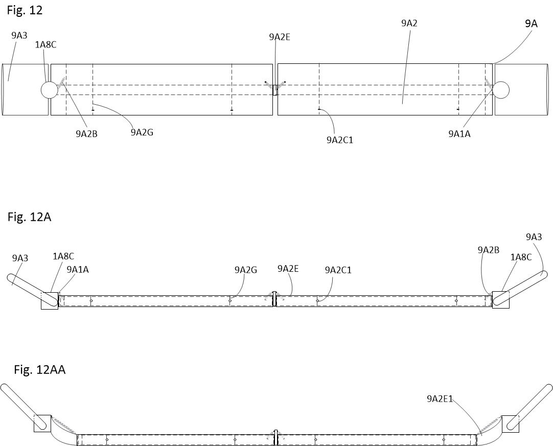
  • Dynamic Incidence Control: Foil winches (9A2C) and counteracting springs (9A2B) rotate foils around central shaft (9A2E) for banking, braking, and submarine depth control.
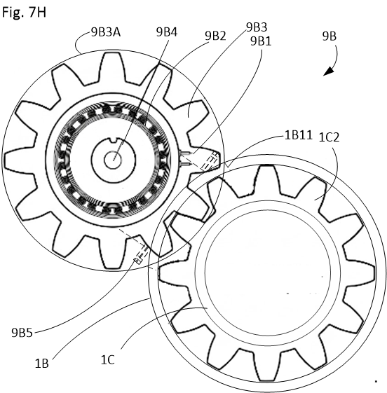
  • Continuous Steer Meshing: Steer-by-wire servo pinions (9B3) mesh through middle cylinder portal (1B11) into elongated geared piston (1C2) across full suspension stroke.
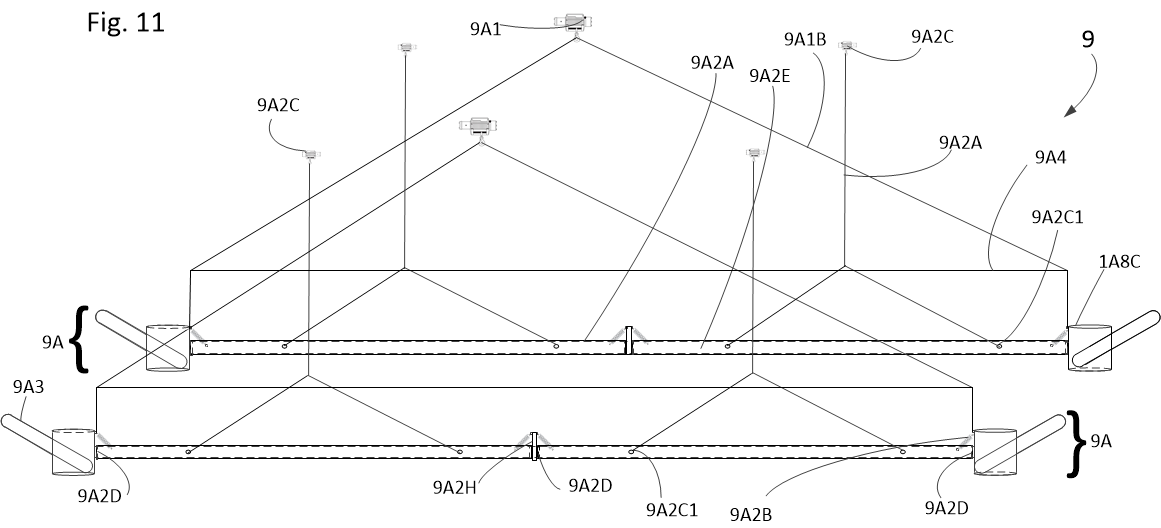
Fig 11 Deployment System Fig. 11 — Winch-Actuated Foil Rigging
Amphibious Transition Sequence

A pushbutton transition executed automatically via onboard ECU processor control.

1

Water Entry & Verification

Load sensors and software prevent unwanted wheel motion when transitioning. Transition lockout prevents activation while in high-speed motion.

2

Electromagnetic Unlocking
The electromagnetic pins are de-energized while in transition so that the springs lock them in when the upper or lower holes are reached.

3

Guided 90° Rotation & Descent

The deployment winches lower two drives and the hydrofoils simultaneously. The electromagnetic pin, travelling along the spiral channel grooves embedded in the upper cylinder's wall, forces a precise 90° axial rotation and vertical descent beneath the keel.
4

Spring-Loaded Re-Locking

Once locked into water mode, power is again returned to the wheels and also given to the foil control winches.

5

Pump-Jet Wheel Spokes

The spiral propeller/pump-jet shaped wheel spokes provide efficient propulsion on the water, structural support to the rim, and augmented cooling for the in-wheel motor.

Commercial & Field Applications

Multi-sector capabilities enabled by the Hydro-Terran drive architecture.

Wildfire Suppression & Irrigation

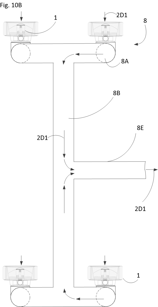
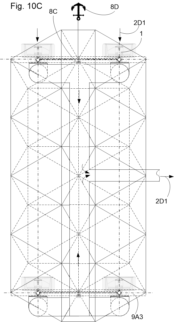
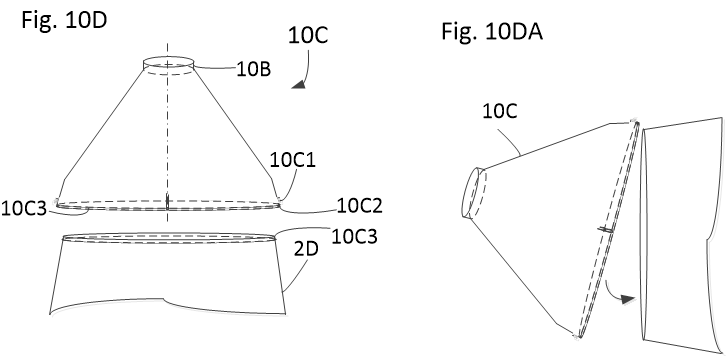
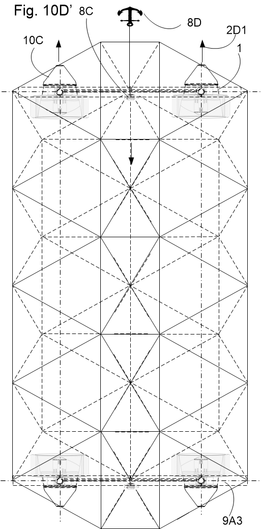
By attaching quick-connect Storz cam-lock adapters (10C) directly to the pump-jet nozzles, each in-wheel motor converts into a high-pressure, multi-thousand GPM water cannon parked directly on a sea, lake, or river.

Submersible & Defense Recon

In a watertight hull with active buoyancy cells, dynamic foil incidence control enables true submarine exploration, silent littoral approach, and 360-degree zero-radius maneuvering.

High-Speed Eco-Transit

Bypassing gridlock by utilizing waterways at highway speeds without water wakes or fuel burn, providing sustainable island, coastal, and remote northern transport.